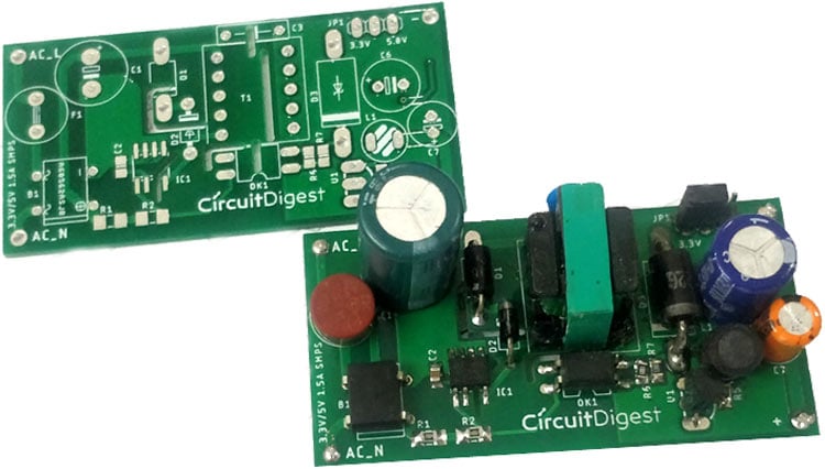
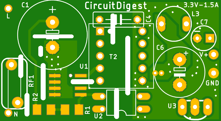
Design your own Compact 5V33V SMPS Circuit for Embedded and IoT Projects Circuit Diagram 1: Input Stage. The AC input supply of frequency (50-60) Hz feds directly to the rectifier and filter circuit.Its output contains many variations and the capacitance value of the capacitor should be higher enough to handle the input fluctuations. Finally, the unregulated dc is given to the central switching section of SMPS in order to regulate it. This section does not contain any transformer Step 13: Test the SMPS. After assembling the SMPS circuit, test the circuit for the output voltage and current, ripple voltage, efficiency, and stability. Adjust the values of the components if necessary. Conclusion. Designing an SMPS circuit requires knowledge of power electronics and some formulas.
successfully layout a printed circuit board (PCB) for a switched-mode power supply (SMPS) • This presentation is relevant to all SMPS PCB layouts, from 1 W to 10 kW • Part numbers mentioned: - UCC28180 - UCC28742 - UCC28710 - UCC24612 - UCC24610 • Reference designs mentioned: - TIDA-00443
PDF Printed circuit board layout for switched Circuit Diagram
Usually in SMPS circuit there is an inductor at the input which decides the input current. In continuous mode, the current in the inductor is continuous in the entire cycle of the switching period. This reduces the size of components required in the circuit design of the SMPS. • Low cost-Because small size components are used to make the
Good knowledge you share please share some practical design SMPS supplies for different voltages and how to design SMPS transformer input and output configuration. Posted on April 13th 2024 | 6:51 am. Hello i need a SMPS circuit diagram that can support 270w of the power and also 20v 13.5amps and also 18v 15amps. Posted on May 10th 2023 | 1

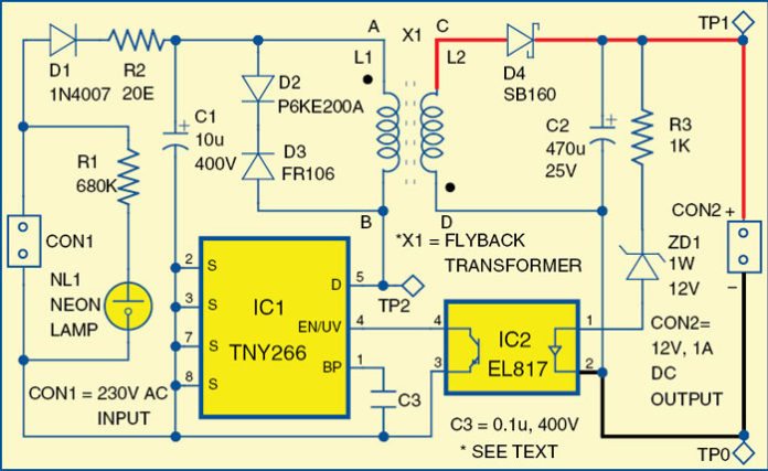
12V 1A SMPS Power Supply Circuit Design on PCB Circuit Diagram
12v SMPS Circuit - Design Considerations. Before proceeding with any kind of power supply design, requirement analysis has to be done based on the environment in which our Power supply will be used. Different kinds of power supply work in different environments and with specific input-output boundaries. Switched Mode Power Supply design given in the form of simple SMPS Circuit diagram, We know SMPS is an essential device for modern electronics, to provide efficient power supply from AC to DC. A Typical SMPS circuit contains Various components like Transistors, Diodes, Capacitors, Inductors and Special Pulse Transformer, those are should meet
